
Moblie: 8613816755915
What are the requirements for steel decking layout drawings
Steel decking layout drawings should be available for those lifting the decking, so that the bundles can be positioned correctly around the frame. Apparently, they should also be available to the deck-laying team.
The bays of steel decking
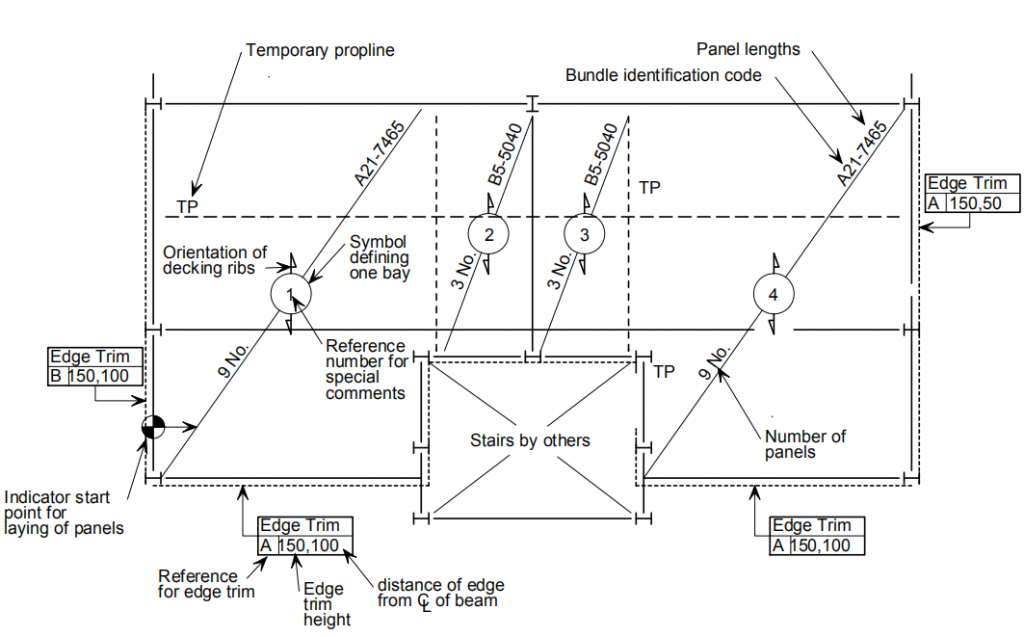
Although different steel decking contractors may have slightly different drawing details, the drawing should (in principle) divide each floor into bays, where a bay is an area that will be laid as a unit. Compartments are usually represented on drawings using diagonal lines. The number of pages and their length should be written on the diagonal. Bundle references can also be specified according to this diagonal. Further construction instructions for the bay can be referred to using the numbers in the circles drawn on the diagonal, as shown in Figure 3.1. This figure shows an example of a floor plan, but shear connector and fastener information is omitted for clarity. The steel decking contractor’s literature should be consulted for exact details.
Directions for laying steel decking
The approximate starting point for the laying of the steel decking, and the direction in which the laying should be carried out, should be given on the drawings. All supports (permanent or temporary) should be determined and whether they should be in place before the decking is laid. The letters TP on a drawing usually indicate a support line. It should also show the column position and its orientation. Deck type, thickness and material strength should be indicated on the drawings.
Opening treatment for steel decking
The location of all openings decorated with steelwork, and the perimeter of all slabs, shall be given with respect to the permanent supports. This can be in the form of a reference box titled “Edge Trim” with reference number (for details shown elsewhere), the slab depth and distance from the slab edge to nearest permanent support center-line, but should refer to trim contract Consult the steel decking contractors’ literature for exact drawing details.
The shear connector layout
For clarity, the shear connector layout should also be shown on the deck drawing or on a separate drawing. Information should include the type of shear connector, length, orientation (if shot), and position relative to the ribs. The minimum distance between the center-line of the shear connector and the edge of the steel decking shall be given. Details of preparation, fixing and testing of shear connections shall be available on site.
Fastener information
Fastener information shall be provided on the drawing. The type of fasteners for joints and supports should be given, together with the maximum spacing (or minimum number of fasteners per meter). If the structural designer designs the pavement to act as an effective lateral restraint to the beams, and the manufacturer’s normal fixing arrangement requires additional fasteners, this should be clearly indicated on the pavement layout drawing and/or general instructions.
The general instructions.
The general description is to include the design loads that the deck can withstand under construction conditions. A copy of the deck layout drawing must be provided to the general contractor in order to check that the necessary supports are in place. The General Contractor will also need to refer to these steel decking layout drawings for details of maximum construction loads and any special loads.