
Moblie: 8613816755915
Analysis of Load-Bearing Wall Studs Under Combined Loading
Metal studs are widely used in structural flaming, such as in load-bearing wall studs. However, selecting the appropriate cross-section and size can be challenging and requires detailed calculations.
When calculating the performance of load-bearing wall studs under combined loads, the AISI S100 standard must be followed. First, identify the relevant loads; then, perform a computational analysis for different load combinations; finally, verify the web crippling and deflection of the wall studs.
Conditions and Related Loads for Wall Studs
Specified (unfactored) Loads: Axial live load (L) = 15.0 kN/stud
Axial dead load (D) =8.0 kN/stud
Wind load (W) =1.2 kPa
Conditions: Stud height = 3.2 m
Stud spacing = 406 mm o.c.
Deflection limit = L/600
Assume studs are braced by bridging only
Solution of wall studs
Based on the data above, select according to the table in the SOLIDECK Studs Catalog: 600S162-54 metal studs at 406 mm o.c.
Dead load only
Factored load combination = 1.4D
Cf (factored axial load) = 1.4D = 1.4(8.0) = 11.2 kN/stud
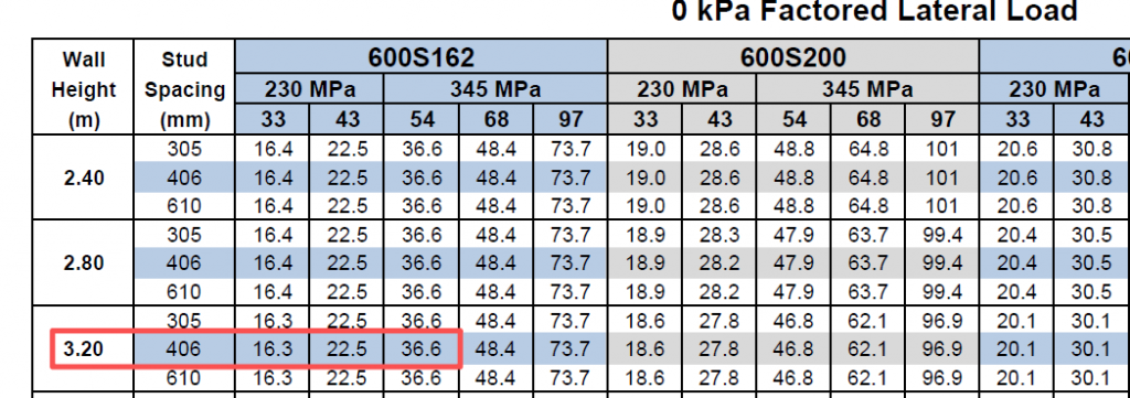
From Combined Axial and Lateral Load table, the limiting factored compressive resistance for 0 kPa factored lateral load.
Cr=36.6 kN/stud
Since Cr = 36.6 kN/stud > Cf = 11.2 kN/stud ∴OK
Dead + Wind + Live Load
a) Factored load combination # 1 = 1.25D + 1.5L + 0.4W
Wf (factored wind load) =0.4W
= 0.4(1.25)= 0.5 kPa
C (factored axial load) = 1.25D + 1.5L
=1.25(8.0) + 1.5(15.0)
=32.5 kN/stud
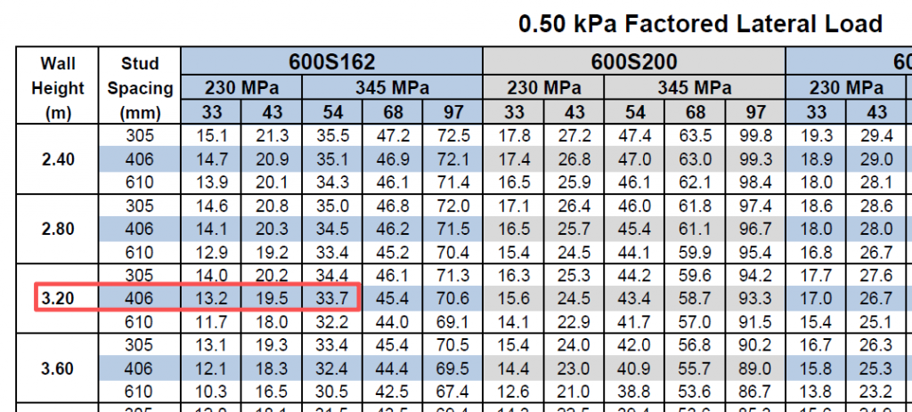
From Combined Axial and Lateral Load table, the limiting factored compressive resistance for 0.50 kPa factored lateral load.
Cr=33.7 kN/stud
Since Cr= 33.7 kN/stud > Cf = 32.5 kN/stud ∴OK
b) Factored load combination # 2 = 1.25D + 0.5L + 1.4W
W f (factored wind load) = 1.4W = 1.4(1.25)= 1.75 kPa
C f (factored axial load) = 1.25D+ 0.5L= 1.25(8.0) + 0.5(15.0)
= 17.5 kN/stud
From Combined Axial and Lateral Load table, the limiting factored compressive resistance for 1.5 kPa and 2.0 kPa factored lateral load
Cr = 28.0 kN/stud (for 1.5 kPa) Cr = 25.3 kN/stud (for 2.0 kPa)
By interpolation for 1.75 kPa, Cr = 26.7 kN/stud > 17.5 kN/stud ∴ OK
Check of wall studs solution
According to AISI S100, checks for web crippling and deflection should also be performed.
Web crippling check
From Single Span Curtain Wall Limiting Heights table for a 1.25 kPa specified wind load, web crippling does not control.
Deflection check
Deflection check is performed based on L/600 of the deflection. From Single Span Curtain Wall Limiting Heights table, the limiting stud height for a specified wind
load of 1.25 kPa and a deflection limit of L/600 is 4.3 m.
Since 4.3 m > 3.2 m ∴OK

Conclusions on the Calculation of Load-Bearing Walls studs
The above outlines the entire calculation process for Load-Bearing Wall Studs Under Combined Loading.According to our calculations,Use 600S162-54 section spaced at 406 mm o.c. with 2 bridging lines arranged so that the maximum spacing does not exceed 1.22 m o.c.